
|
MiraMon horizontal reference systems. |
Horizontal reference systemsIn a Geographic Information System (GIS), the horizontal reference system (SRH) serves to define the frame of reference (origin, units, etc.) from which the linear or angular quantities assigned to the position that occupy each point in a two-dimensional space X, Y are measured, where the objects and phenomena stored by the GIS are represented. In other words, given an X, Y coordinate of the map, the SRH lets the user know where it is measured, in what units, etc. MiraMon horizontal reference systems are classified as: local and cartographic. The local SRH are used in simple cases as a plane of a farm measured in meters from an origin located in one of its angles, or as a scanned map measured in pixels and as the origin the lower left corner of the raster generated in the scan. The local SRH do not have any special complexity and do not require practically any other technical specification. However, local SRHs are unsuitable for cartographic applications, in which the extension of the territory treated, the need to make the information cross-link with other sources, etc., require adopting the procedures and conventions that, since many years, have been established by Cartography and Geodesy. These procedures and conventions make cartographic SRHs much more complex than local SRH; it must be understood, however, that this complexity is necessary to make the transformations between the terrestrial surface (curve, etc.) to a certain cartographic projection, datum, ellipsoid, etc. This document describes the cartographic SRH type. In MiraMon, layers can be documented in any cartographic reference system; However, in order to recognize the system and show latitude/longitude coordinates, visualize a network of meridians and parallels or transform the layer to another projection or to another reference system, an identifier, called horizontal reference system identifier, must be associated. This identifier allows to completely describe the properties of the geodetic system underlying any cartographic SRH type. However, for this to be possible, the identifier must meet one of the following conditions; evaluated in the same order in which they are presented. In other words, when the metadata of a layer is read it shows the SRH identifier that consists of following the conditions presented until an association is found:
If any of these conditions are met, the SRH identifier is linked to horizontal units, a datum, an ellipsoid, a cartographic projection and valid parameters for this projection. If no association is found, the SRH is considered to be local and not cartographic.
Geodesic tables and filesMiraMon provides a set of geodesic tables: the geodesic tables of MiraMon. These tables cannot be edited and MiraMon reserves the right to introduce extensions and modifications in future versions. The names of the MiraMon tables begin with the characters "m_". The user can introduce new reference systems, new datums, new ellipsoids or new projection parameter values in the user geodesic tables. The names of the user tables begin with "u_", present the same structure to the MiraMon geodesic tables and can be created from the MiraMon tables, copying each table and deleting all the records. The following table indicates the names of the tables and a small description that will be expanded in the next points of this document:
All tables are in dbf format and can be viewed with MiraDades (MiraD.exe) except the table of projection parameter values (m_valprj.ini and u_valprj.ini) which is a file in ini format (rel) editable with the NotePad (notepad.exe). These tables are: 1. GEODES: Geodesic table The number of datums, ellipsoids, projections and values for valid projection parameters by the system is practically unlimited, as will be seen later. However, for each region of the Earth, cartography is expressed in a small number of horizontal reference systems and, generally, there is only one system that, over time, has been established as a standard, often by law, in a territory. For this reason, and to facilitate the use of the system, it is provided a table that allows to define, from the datum identifiers, ellipsoid, projection, etc., a reduced number of entries that represent a subset useful for the user work environment. This is the MiraMon geodesic table (m_geodes.dbf). The user can extend this set with a user geodesic table (u_geodes). The table defines each SRH identifier from horizontal units (field UNITATS), a projection identifier (field ID_PRJ), a projection parameter identifier (field ID_VALPRJ), a datum identifier (field ID_DATUM) and a identifier of the alternative ellipsoid (field ID_ELL_ALT). A datum already has its ellipsoid (never a sphere) associated with the table m_datum.dbf, field ID_ELLIP. For this reason, the alternative ellipsoid field (ID_ELL_ALT) is usually left blank in most cases. Essentially, the field ID_ELL_ALT is designed to be able to apply spherical projection models. When the alternative ellipsoid is defined, it is only applied in the projection change process (map coordinates to longitude/latitude) but not in the change of the datum (step to geocentric coordinates), where the ellipsoid associated with the datum is always used. 2. PARDTM: Datum parameters table for a specific region Each SRH identifier must have the datum correctly defined. This complete definition should not indicate only the geodetic datum, but also the optimal parameters of local transformation between this datum and WGS84 and between WGS84 and this datum. For this purpose, the field ID_DATUM of the geodes tables (m_geodes and u_geodes) contains a datum identifier that allows access to the complete definition of the datum through the homonymous field of the parDtm tables (m_ParDtm and u_ParDtm). As previously stayed, in these tables the datum is defined in a complete way informing of the datum that has been used (ED50, NAD27, etc) as well as of the transformation parameters between this datum and WGS84 and from WGS84 and this datum, which have been calculated optimally for each specific region that has a datum identifier. The datum that has been used (ED50, NAD27, etc) is not completely described in this table, since this would imply a great redundancy for the different datum identifiers that are used in the same datum but different transformation parameters with respect to WGS84. The different datum identifiers that use the same datum (but different transformation parameters with respect to WGS84) constitute a "group". This is why the field ID_GRUP of the tables ParDtm allows to indicate the "group" of the datum used (ED50, NAD27, etc.) which is specified in the datum tables (see below). The transformation parameters between the datum and WGS84 and between WGS84 and the datum for each datum identifier can be of Molodenski (if only the geocentric displacements X, Y, Z between datums are known), or of Bursa-Wolf (if the rotations and scales are also known). They are indicated in the following fields of the datum tables:
The last four points are left empty to describe the Molodenski parameters. There is the possibility of defining the error associated with each of the above parameters, for example S_DELTA_X will correspond to the error in DELTA_X, both in the direct and inverse directions. For some datums there are specific parameters adjusted in a particularly optimal way, for different areas of the Earth. The LLOCS field specifies the application areas of each set of parameters. 3. DATUM: Datums table This table contains the different datums used in cartography without any parameter conversion between them nor with WGS84 (see tables ParDtm for this purpose). As explained when referring to the ParDtm table, various datum identifiers are grouped around the same geodetic datum. So the key field of this table is called GRUP_ID, with which the homonymous field of the ParDtm tables are linked. DATUM tables describe the datums and indicate the ellipsoid associated with each datum. 4. ELLIP: Ellipsoids table Most commonly the reference system uses the ellipsoid associated with its datum, both for the transformation of map coordinates to longitude/latitude coordinates and for the transformation to geocentric coordinates. This ellipsoid is specified in the field ID_ELLIP of the data table, which links to the table of elipsoids m_ellip.dbf or u_ellip.dbf. There are databases that due to their continental or global extension and their low resolution use a spherical projection system. In this case the user can force the use of an alternative ellipsoid (only used in the coordinate map to longitude/latitude), introducing it in the ID_ELL_ALT field of the geodesic table (which is otherwise empty). This identifier also links to one of the ellipsoid tables. The parameters needed to define an ellipsoid are:
If order to describe a spherical model, users must introduce the radius as a semi major axis and leave empty the inverse flattening field. 5. PRJ: Cartographic projections table The systems indicated in the geodesic tables (m_geodes.dbf and u_geodes.dbf) must be linked with the projection table m_prj.dbf through the ID_PRJ field. In this case there is no user table; MiraMon can only support those projections already defined in this table. If the user wants support for a projection not currently implemented, users can request its coding at suport@miramon.cat. Otherwise, it allows defining as many sets of parameters of each projection as necessary (for example, spindles of the UTM projection or equidistant parallels in the conformal conical Lambert). Each projection has associated units by default. Additionally, the following geometric properties have been described to inform the user:
For these properties the value 0 indicates absence, 1 indicates that the property is met in certain locations or addresses, 2 indicates that the property is partially fulfilled and 3 indicates that the property is preserved throughout its domain. 6.PARPRJ: Projection parameters table The table m_prj.dbf links to the table m_parprj.dbf, where the parameters of each projection that can receive values with units are found (note that there are no user tables from the tables m_parprj and m_prj). The table m_parprj.dbf also has the functionality to describe the geodetic meaning of each parameter of the projection and to control the range of its possible valid values. 7.VALPRJ: Projection parameters A given SRH will take concrete values of the parameters defined to m_parprj by its projection system. These particular values are defined in the m_valprj.ini and u_valprj.ini files in the following way: The reference system defines a "set" of parameters in the ID_VALPRJ field of the geodesic table corresponding to the "prj" projection of the ID_PRJ field. This set of projection parameters links to the [prj:joc] section of one of the files m_valprj.ini or u_valprj.ini. In this section, each of the possible parameters of the projection, defined in m_parprj.dbf, will be a key with concrete value. If this parameter is missing it will take the default value. In summary, each projection can be parameterized in many ways: the reference parallels in certain conical and cylindrical projections, which meridian is assigned to the coordinate X=0, etc. The field ID_PRJ of m_geodes indicates the projection itself (and at the same time, users can know which parameters should be given by consulting the table m_ParPrj for the records that have the same value in the ID_PRJ field of this table). However, the projection is specified (which value each of the m_ParPrj parameters takes) through the m_ValPrj.ini file, which contains sections with the combined name [ID_PRJ: ID_VALPRJ] which, in turn, contain, in their keys, the parameters values (for example "fals_est=600000" or "lambda_0=0.0"). Scheme and example The relational scheme of the geodesic tables and files in MiraMon can be summarized as:  For example, the UTM-31N-UB/ICC reference system would correspond to a scheme like the following: 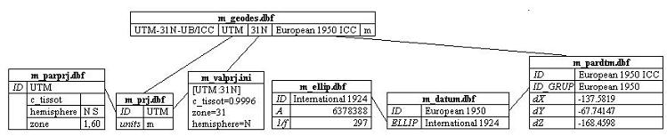 Notes: To correctly interpret the reference system names of MiraMon versions prior to 4 or to identify equivalent terminology that come from some imports of other softwares, there are official identifier tables: m_idofic.dbf and u_idofic.dbf. The field PSIDGEODES contains the previous or alternative name, while the field ID_GEODES contains the official name that links to one of the tables m_geodes.dbf or u_geodes.dbf. For example, if there are many bases documented with the SRH UTM-31N, users can define that UTM-31N is equivalent to (synonym with) UTM-31N-UB/ICC. It must be kept in mind the hierarchy of the geodetic scheme to avoid possible redefinitions. An SRH is unambiguously identified by its key field ID_GEODES. If there is a repetition of this identifier between the geodesic tables and/or between a REL corresponding to a particular layer the following rules are followed: first the identifiers in the MiraMon table m_geodes.dbf prevail, second those in the particular REL of the layer, and third those in the user table u_geodes.dbf. If users want to create a reference system different from those defined by MiraMon, the user must assign a different identifier to the user table and make it correspond to the rest of the geodesic elements. Given that the name of possible horizontal reference systems based on combining projections, parameters, datums, etc., is long, the official MiraMon tables (file m_) only collects the most used systems among users. This allows the number of options available in the drop-down to be non-intractable. Thanks to the existence of user tables (files u_) each user can perfectly define their system and see it in the drop-down as a system about to be used. However, the users who consider that their reference system is very universal, or used by many users, and in particular those institutions that disseminate Internet cartography through the Miramon Internet Map Publisher technology (MMZ format and the MiraMon Universal Map Reader) can request to suport@miramon.cat incorporate its system among the systems present in the "m_" tables that are distributed with MiraMon and with the "MiraMon Universal Map Reader". The user can have different tables and geodesic files keeping with their names in different locations. A MiraMon session or any module (MSA) has always defined the working directory (see Help | Work Directory in the MiraMon menu). The tables or files located in the working directory are saved. If they are not located in the working directory, existing ones are used in the directory where the program has been installed (typically C:\MiraMon). The "m_" geodesic tables are supplied by MiraMon and should not be modified. It is possible to define a new user reference system in tables "u_" or directly in the REL file. MiraMon does not provide user tables, but they can be created by the user and add new reference systems to them. However, take care when modifying the structure of the user tables: it is allowed to add fields with new information and change the order of the fields, but other modifications could make the whole geodesic scheme unusable. In those tables where there is a field named SRC, the data source of each record must be indicated. In future versions, interfaces will be provided to add, in an assisted way, new reference systems or to make some modifications to the existing ones. Currently it is necessary to understand the whole relational scheme and manipulate the tables directly with MiraDades. Users can create new entries by duplicating an existing record that be similar to the new system and modifying the contents of the fields in the new record. Some fields in the geodesic tables have an associated description field. The content of this field can be a direct string of descriptive text or it can be a string in the style STB#Desc. This second case, used for an improved idiomatic maintenance, implies that the record in question, points to a descriptor that will be found in the general.stb file.
Finally, it should be noted that layer transformations are supported for MiraMon own formats, IMG for rasters, and PNT, ARC/NOD, POL, or VEC for vector cases. In order to transform a layer into any other format, the user must import it through the corresponding "File | Import" module (TIFIMG, DXFVEC, etc). This document is only helpful for the user on concepts and geodetic mechanisms that have been implemented in the MiraMon GIS and does not pretend to explain geodesic concepts, transformations, properties, etc. Consult a good manual of cartography and/or geodesy for more details. |
