|
In MiraMon, any representation of the cartographic space that is made by symbolic representation through points, lines or polygons is treated as a vector. MiraMon supports non-structured and structured vector files. Structured vector files may have explicit topological relationships.
Non-structured vector files are text files (ASCII) that “simply” contain geographic entities, but without an internal structure to allow fast access and query, or explicit topologic relationships between objects. They contain a single attribute and are not linked to a database outside the file. MiraMon non-structured files are directly compatible with ASCII vector files from the Idrisi v. 4.x software and have the advantage of being simple to create and edit, and they are also easy to export and import.
On the other hand, structured vector files are binary files with an internal structure to allow fast access and query, and explicit topologic relationships (i.e., they are able to know about the existence of several holes inside polygons, to know which polygons are in the neighborhood of a given polygon, to know which lines are in contact with other lines, or they can even connect disjoint islands that have to be considered together). They are linked to databases and therefore they allow to carry out complex analyses of the information quickly. They can contain 1-to-many relationships at any level of the relational tree (for example, a graphic element such as a cadastral parcel can be related to as many records (owners) as needed). From MiraMon version 4.0 on, it is possible to access any database, for example, MS-Access, Oracle, SQL Server, DB2, EXCEL, DBF and many more, using the Microsoft ODBC technology to read it. The vector formats that MiraMon can open directly are its own formats (PNT, ARC/NOD and POL) and SHP, DXF, GPX, KML, DGN and GML; for the sake of speed access, these formats are structured, but not topologically structured when are read for displaying them, but can be converted in true topological datasets with the appropriate MiraMon tools. Additionally, an extensive number of other vector formats can be incorporated via import as E00 (vector), ArcSDE, SDO (Oracle), VEC (Idrisi), CDF (NetCDF) and any import of data coming from a GNSS (GPS) receiver. Please refer the Import option in the "File" menu for more information. Before MiraMon version 4.0, the only format for the database was the DBF format.
We can summarize the differences between non-structured and structured vector files as follows:
| Non-structured: |
- They never contain explicit topological information between the objects.
- They contain a single attribute and they are not linked to an alphanumerical database.
- They are text files (ASCII).
|
| Structured: |
- They can contain explicit topological relationships between the objects, or be internally structured optimally for quick access, etc, but not contain explicit topological relationships.
- They are linked to an alphanumerical database, that can be relational and contains as many attributes as needed.
- They can contain 1-to-many relationships at any level of the relational tree.
- They are binary files and consequently, together with its internal optimized structure, information can be accessed quickly.
|
 The following description explains the structured files from a user point of view. Fore a more technical explanation (internal format, etc) and conceptually deeper (types of topological relationships, etc), the technical document: Structured vector file format (topological or not) in MiraMon can be consulted. The following description explains the structured files from a user point of view. Fore a more technical explanation (internal format, etc) and conceptually deeper (types of topological relationships, etc), the technical document: Structured vector file format (topological or not) in MiraMon can be consulted.

The MiraMon non-structured vector format is based on a text (ASCII) file. In this file, it is only necessary to save the thematic attribute of each object, the number of coordinates representing it and the coordinates of each vertex.
These vector layers are created from two files:
a) The first file contains the graphic representation as well as a single attribute for each geographic feature and has a .vec extension. Its structure is a repetition of the following plan as many times as objects (points, lines or polygons) are contained in the file:
Attribute Number_of_vertices
CoordinateX CoordinateY [CoordinateZ]
: : :
In the case of point files, Number_of_vertices is always 1. In the case of polygon vectors, the last coordinate is the same as the first one and, therefore, closes it.
Two final zeros separated by a blank on a new line indicate the end of the file:
0 0
These VEC files look like the ASCII format files of Idrisi software up to v. 4.x, but there are some differences:
- They support double precision coordinates (15 to 17 significant figures).
- They support "long" attributes (values between -2147483648 and 2147483647) [referred to as "long" or as "integer" in the DVC "id type" key ] as well as "integer" attributes (values between -32768 and 32767) [referred as "integer" in the DVC "id type" key ] and "real" attributes (values ±3.4E±38, with 6-9 significant figures) [referred to as "real" in the DVC "id type" key ]. They can support "long" attributes because they can treat them as identifiers and not as simple attributes, turning them into true indices in a database file (for import/export compatibility). So the format is limited to 32767 objects in each layer, but can have up to 2000 millions of objects; the first limit can be easily reached in classified remote sensing images when they are vectorized.
- They can support "string" attributes, which are documented as "string" type in "id type" key of the DVC file.
- They are always text files (not binary).
b) The second file contains metadata information: type of object (point, line or polygon), extent, units, etc, and it has .dvc extension. Its format is compatible with the formats used in the Idrisi v. 4.x. software; however, MiraMon has some extensions and restrictions. Its general structure is shown below:
file title: Title
id type: integer (or long or float or string)
file type: ascii
object type: point (or line or polygon)
ref. system: UTM-31N-ETRS89 (or plane or any other reference system)
ref. units: m (or pixels)
unit dist.: 1.000000
min. X: 414791.000000
max. X: 428809.800000
min. Y: 4585571.000000
max. Y: 4594974.200000

Structured vector layers are based on files stored in an own binary format developed by Xavier Pons and Joan Masó. In short, there are three main families or types of topologically structured vector layers: points, arcs and nodes, and polygons.
- POINTS: These layers contain point type entities which are described by a single coordinate (x,y) or (x, y, z).
- ARCS AND NODES: These layers contain arc type entities which are lines described by a series of segments, each one defined by coordinates (x, y) or (x, y, z) and, when topologically structured, they are never intersected nor in contact with other arcs from the same graphic dataset, or only in contact at their extremes (called nodes). Each coordinate is called a vertex, and the line, which is always straight, that joins every pair of vertices is called a segment. As said, both extreme vertices of each arc are called nodes. Each arc has to contain a minimum of 2 vertices (and in this case, they have to be different and form a single segment). In other terminologies, an arc is also called a chain, string or polyline, and these terms are also used in a broader sense and even to mean different things.
Even though it is not the typical case, in MiraMon it is also possible to use structured files to store entities that have not been topologically structured,e.g., line files containing entities in which it is possible to have non-explicit intersections, point files where the spatial uniqueness have not been checked, etc. In this case, the file header is aware about that, and the user can know it through the “Presentation | Technical aspects” tab of the Universal Geospatial Metadata Manager (GeM+), or by loading the layer in MiraMon and executing "Information | Opened Vectors"; in both cases an explicit text, as “guaranteed topology” or “NOT guaranteed topology”, is shown.
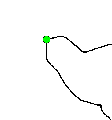
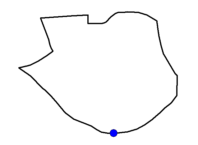
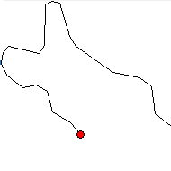
Sometimes we want to differentiate the nodes according to which arcs or in which number they converge, as this has implications for the topological relationships in the plane. Therefore, it is possible to differentiate four types of nodes depending on their function.
-Typical node: This is a node that connects three or more arcs of any type, or even two or more arcs (in that case at least one arc has to connect to the node by its two extremes).
-Linear node: This is a node that connects two and only two arcs, and it is only connected once to each arc. It is used to separate two arcs that have different attributes and need to be kept separate in the alphanumeric database (in other software or formats, line nodes can appear because the maximum number of vertices per arc is small (e.g., 500) and has been reached).
-Ring node: This is a node that connects only one arc. This arc closes itself by joining its two extremes.
-End Node: This is a node that connects only one arc on only one extreme.
 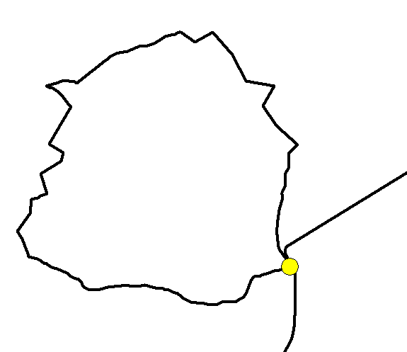 |
 |
 |
 |
| Typical nodes |
Linear node |
Ring node |
End node |
In MiraMon, when we talk of "nodes" we refer to any type of node, whether it is "typical", "line", "ring" or "end". In the database there is a field called TIPUS_NODE (NODE TYPE) that codifies these four node types, respectively, using the numbers 0, 1, 2 and 3; a small thesaurus can be made in order to read "typical node", "line node", etc. instead of 0, 1, etc. Nevertheless, their names are automatically generated in the legend, and even the codes may be forced to appear by activating “values” in the “Visualization of the LAYER in the legend” dialog box:
In MiraMon the ARC layer is always associated with the NODE layer.
- POLYGONS:
- These layers contain polygon type entities, which are closed shapes described by one or more arcs. Sometimes a polygon has holes inside it; in this case, it is termed a polypolygon and all the polygons that form it (the outside polygon and each of the polygons that outline the inside holes) are termed elemental polygon (or "ring" or "outline"). When using simply "polygons", we are referring to any type of polygon, whether it is formed by the several elemental polygons or only by one polygon.
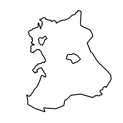 |
| Polypolygon |
A topological polygon is not defined directly by its vertices, but rather it is defined by the sequence of arcs that form it. The basic process to build the polygon topology starts building the arc-node topology and cycling all the arcs until all the regions are closed.
MiraMon allows the creation (cycling) of more than one polygon layer from the same arc dataset. A typical example is an arc dataset that defines municipal boundaries. As normally municipalities are part of larger groups (counties, regions, provinces, countries, states, state communities, etc.), therefore it is possible to cycle the polygons that form the municipalities, those that form the counties, etc, from the same arc dataset. This saves storage space and provides better data consistency: if a municipal boundary changes or is defined precisely, the regional, national etc, boundaries that are also formed by this modified boundary, will automatically change. This MiraMon characteristic implies that the metadata file has to indicate over which arc dataset the polygon file is cycled. Note that the different polygon layers created from the same arc dataset do not use the same arcs (or at least not all of them).
A layer that contains objects from one of these families is formed by a certain number of files, and some of them are specific for some of these families. However, there are three files that are common to all families, and they are described below:
- Graphic elements file: This file contains the graphic database with the coordinates that define the vectorial entities, as well as their topological relationships (spatial relationships), if needed. It is always a binary file. The extension of the graphic file depends on the family being treated. The family and the corresponding extension are shown below:
Family |
Extension |
Points |
*.pnt |
Arcs |
*.arc |
Nodes |
*.nod |
Polygons |
*.pol |
-
Main table: This file contains the main table of the database in dBASE (DBF) format, or in extended DBF if needed. It can contain any type of field, but MiraMon will only show the following ones: Numeric (N, allows integer numbers and real numbers with practically any extension or precision), Character (C), Logic (L) and Date (D). The Memo type fields, OLE, etc., are ignored. The extension of the main table file depends on the family which is being treated and it is shown below:
Family |
Extension |
Points |
*T.dbf |
Arcs |
*A.dbf |
Nodes |
*N.dbf |
Polygons |
*P.dbf |
This table identifies the objects it contains with a single numeric code. This code is an integer value numbered from 0 (zero) that represents the graphic identifier. The graphic database never contains two elements with the same graphic identifier or discontinuities in the numbering of the elements: the order forms a strict ascending monotonous series. In other terminologies, the graphic identifier is also called "internal identifier". The graphic identifier can be in any of the fields of the alphanumeric main table (even though it is usually in the first one) and it can have any name (even though it is usually called ID_GRAFIC), but it has to have two characteristics: it has to be of numeric type (N) and it has to be ordered in ascending order (if needed, it can be ordered using MiraDades). Any external table or database can be linked to the main table through a field that acts as a link. This link (dynamic join) operation can be set in the “Thematic information” tab of the Universal Geospatial Metadata Manager (GeM+) using the mouse right button. At the same time, any linked table can be linked again through any of its fields using the same procedure. Moreover, a field can be linked to more than one database, and it is possible to set links from as many fields of a table as needed. Finally, it is also possible to define, for each link, the cardinality of the relationship (1 to 1, many to 1, many to 1 assuming the relationship will be always possible [to a dictionary], etc).
The ID_GRAFIC field will contain only integers, although the following features are supported:
-Negative numbers are allowed (consequently, not linked to any graphic entity).
-Numbers greater or equal than the number of graphic entities are allowed (so, not linked to any graphic entity).
-More than one record per graphic object is allowed; this is called multiple record. In other words, setting a cardinality of 1 to many from the graphical to the alphanumerical database is possible. Example: Imagine a dataset of water analyses periodically carried out on the different sources of a natural park: each source will have as many records as analyses done on that source (note that this schema is not possible in typical Shapefiles, nor in most other formats).
-"Holes" are allowed in the series (graphic entities that do not have any associated record in the alphanumeric database). This situation is not ideal, but is tolerated because, for example, perhaps not all the sources in the previous example, will have water analyses available.
If the main alphanumeric table contains records that will never be associated to any graphic entity, it can be useful to simply assign a negative identifier to them (even if it is always the same, such as -1). Nevertheless, remember that after adding new records the database should be sorted again (with MiraDades, orderby, etc, depending on the software) using the field containing the graphic identifier as the key field (or adding these records in the proper, ordered, position). The main table also contains other fields, termed geometric-topologic fields, which contain geometric or topologic attributes of the graphic objects. For example, the main table of a polygon layer usually contains the area and perimeter of each polygon, the number of elemental polygons that comprise the layer etc, while the main table of an arc layer usually contains the length, the identifier of the "from-" and "to-" nodes, etc. All of these fields are maintained by MiraMon and the user never has to edit its type or contents.
The database tables can be in DBF format (including extended DBF, a practically unlimited extension of the classical format) or in any format that is accessible through the ODBC standard (MS-Access, Oracle, SQL Server, MS-Excel, etc). However, the main table has to be in DBF (classical or extended) format. If all the thematic attributes in one or more tables in other formats have to be kept, simply define a field both in the main table and in the first table of the linked tables in other formats, and make this field acts as an entity identifier (ID_ENTITAT). A 1 to 1 or 1 to many relationship have to be set between the two tables, depending on the needs. In this way, the main table can end up containing only the ID_GRAFIC field, the geometric-topologic fields and the ID_ENTITAT field (this field is called the user identifier in other software).
- Metadata, relations and symbolization file: this file contains additional data about the data, the relations of the database and the visualization description (symbolization). The extension also depends on the family (geometric type), and it is shown below:
Family |
Extension |
Points |
*T.rel |
Arcs |
*A.rel |
Nodes |
*N.rel |
Polygons |
*P.rel |
The metadata file is a file in Windows INI format, made up of sections and keys. This file can be edited with any text processor (Notepad, etc), but due to its complexity, it is best to populate documentation using the application Universal Geospatial Metadata Manager (GeM+). Inside each section, there are a series of keys followed by an equal sign and a value or chain of characters. These keywords allow to define the information that the metadata has to contain. The order of the sections throughout the file and the order of the keys inside each section is not important in order to correctly interpret them and it is not necessary that they are all present. The REL format, characterized by the presence of the [VERSIO] section with the keys "Vers=" and "Subvers=" allows an extraordinarily flexible relationship scheme between the tables, so that each field can link to an unlimited number of tables and then each newly associated table can then be associated with an unlimited number of other tables through its fields. This scheme allows an unlimited number of levels and allows the access to different databases simultaneously, which can be in DBF format or in any format that can be accessed through the standard ODBC standard (MS-Access, Oracle, SQL Server, etc.).
In the current version of MiraMon, the main sections supported in the metadata files of the topologically structured vectors (.rel) are:
- [VERSIO] -> Section that describes the version and subversion of the REL file.
- [METADADES] -> Section that describes the general characteristics of the metadata, such as the language or languages of the metadata, the date of creation, the character set or the unique identifier of the file.
- [METADADES:ORGANISME_#] -> Section that describes the organism that publishes the metadata. The # symbol is the number of the organization that has participated.
- [TAULA PRINCIPAL] -> Section that describes which field of the main table file (DBF) has the graphic identifier and, therefore, acts as a link between the main graphic entities and the alphanumeric database. This information is compulsory and is expressed as follows:
IdGrafic=NOM_CAMP (where "NOM_CAMP" is the name of the field of the main table that contains the graphic identifier).
- [TAULA_PRINCIPAL:NOM_CAMP] -> Sections that describe the information of each existing field in the main table (there are so many sections of these as fields). They allow to decide if the field is visible, symbolizable, the units to show, etc.
- [IDENTIFICATION] -> Section that describes the title of the layer, etc.
- [OVERVIEW] -> Section that describes, among other things, the date where the dataset was created, the updating data, a summary as well as data about the coordinator, promoter, editor and distributor of the database.
- [OVERVIEW:ASPECTES_TECNICS] -> Section that describes, among other things, the file type, the data model, the type of object (points, arcs, nodes, polygons), the number of objects, the alphanumeric database, as well as comments.
- [GEOMETRIA_I_TOPOLOGIA] -> Section that describes the fields that contain the geometric and topologic attributes of the layer.
- [SPATIAL_REFERENCE_SYSTEM:HORIZONTAL] -> Section that indicates the type of horizontal reference system (cartographic or local) and its description, units, projection, datum and ellipsoid, etc.
- [EXTENT] -> Section that describes, among other things, the extension of the database (the envelope coordinates) as well as the center of the scene.
- [QUALITY:LINEAGE:PROCESS_#] -> Sections that describe the different processes carried out in the database (creating polygons with a topological structure, layer joining, etc.), the entity that has performed the processes and the process data. The symbol # is the number of the process carried out in the base according to the order in which the processes have been carried out. The first process is always the number 1 and the following processes are numbered consecutively.
- [TAULA_PRINCIPAL:NOM_CAMP] -> Section that describes the characteristics of a particular field (ID_GRAFIC, N_VERTEX, PERIMETRE, AREA, COLOR, etc.), like the field describer, if the layer is visible and/or can be symbolised, etc.
- [TAULA_NOM_TAULA] ->Section that describes, among other things, the links between the main table and other tables, and the field that is used for the link.
- [TAULA_NOM_TAULA:NOM_CAMP] -> Section that describes the characteristics of a particular field of the linked table.
An example of a P.rel file (vector of polygons of a PEIN base) can be consulted here. For complete information consult the help of the Universal Geospatial Metadata Manager.
In the versions of MiraMon before 4.0 there was an additional documentation file (with extensions *.dvt, *.dva, *.dvn and *.dvp for the families of poinTs, Arcs, Nodes and Polygons, respectively) that have been absorbed in the corresponding documentation file *.rel. This was a file of flat text that can be edited using any text processor (Notepad, etc).
As it can be seen, the DBF and REL files have a T, an A, an N or a P as the last character in their name, depending on if they correspond to the database of poinTs, Arcs, Nodes or Polygons. This characteristic is necessary to support the not unusual possibility of the different types of graphic database having the same name. For example, suppose that there are the Veget.pnt and Veget.arc files; in this case, the DBF and REL files would have the same name for both layers, which is not possible (one overwrites the other); the problem is avoided by defining the names as VegetT.dbf, VegetT.rel, VegetA.dbf and VegetA.rel.
Below there is a summary of the files that each type (families) of topologically structured vectors has to contain:
Family |
Graphic File |
Main Table |
Metadata File |
Points |
*.pnt |
*T.dbf |
*T.rel |
Arcs |
*.arc |
*A.dbf |
*A.rel |
Nodes |
*.nod |
*N.dbf |
*N.rel |
Polygons |
*.pol |
*P.dbf |
*P.rel |
For performance reasons, the different graphic files (PNT, ARC, etc) are binary and according to a predefined format. This format is open and free. Please refer to Technical notes for details.

|

