-
 Thiessen: Generation of Thiessen polygons
Thiessen: Generation of Thiessen polygons| Presentation and options | Dialog box of the application |
| Syntax |
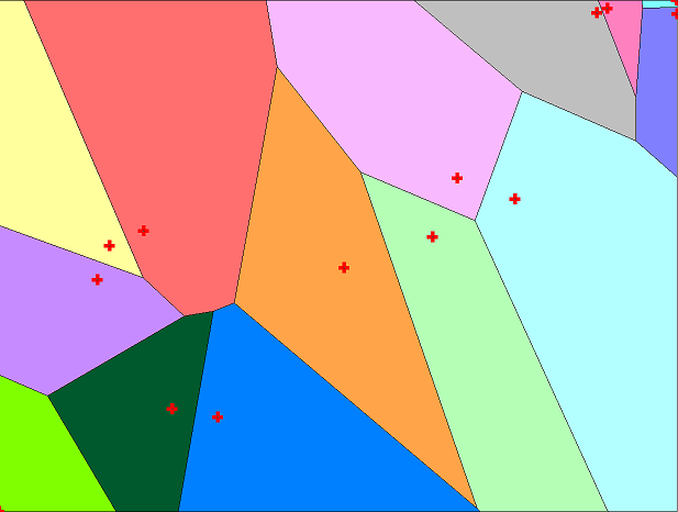
This application generates, from a layer that contains a set of point-type vector entities, a layer of polygons that will contain the corresponding Thiessen polygons.
Thiessen polygons result from generating a partition of space into areas of proximity around the provided points, where each resulting polygon defines the closest area to each point. Thus, Thiessen polygons are the method typically used to interpolate categorical data collected at sampling points (for interpolation of quantitative data collected with sampling points, use the InterPNT: Interpolate between points application).
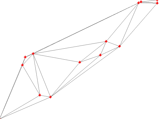
In the Thiessen application the proximity to each point is determined by Euclidean distance. For this purpose, first the program constructs a Delaunay triangulation joining the origin points (as provided by the CreaTIN: Generating a TIN from a point cloud application). Starting from the midpoint of each side of each triangle, perpendicular lines are drawn that, once intersected with the other perpendiculars of the other sides and discarding the segments beyond the intersections, will form the sides of the polygons (the intersections will be the vertices of the polygons).
Once the entire area has been tessellated, each polygon inherits the attributes of the single point left inside it. Additionally, adjacent polygons that have identical attributes in the given database field specified by the user are merged (so there may be polygons that contain more than one of the original points when those points have the same attribute).
The application allows the creation of Thiessen polygons from all the points of the origin layer or to perform a selection by attributes to obtain a subgroup from which to perform the triangulation.
For example, a polygon layer can be created from health care facilities in a certain area. The result, shown in the image below, will be a polygon-type layer corresponding to the influence area of each selected healthcare facility.
The bounding box of the resulting file can be set either from the envelope of the points, or by specifying the coordinates of a rectangle (which can be automatically inherited from the bounding box of another layer), or by providing a layer to act as a mask. In the latter case, the layer can be a polygon layer (in POL or VEC format) or a raster (in IMG format, in which the bounding box of the cells with data acts as the region of interest).
The program can, optionally, keep the layer with the Delaunay triangulation that has been used to build the polygons. This is especially useful in educational environments for a better understanding of the origin of each polygon. The following image shows the Delaunay triangulation applied in the previous example of creating the influence areas of healthcare facilities.
Note 1: Since Delaunay triangulation does not provide a single solution in certain point distributions, it may happen that the resulting Thiessen polygons with this application be different from those obtained with other computer applications.
Note 2: The name comes from the meteorologist Alfred H. Thiessen; the polygons obtained are equivalent to the Voronoi tessellation (from the mathematician Georgy Voronoy) and to the Dirichlet tessellation (from the mathematician Johann Peter Gustav Lejeune Dirichlet).
For more information, see the following reference:
https://en.wikipedia.org/wiki/Voronoi_diagram

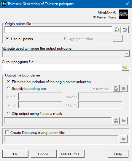 |
| Thiessen dialog box |