
 |
Copy to clipboardMiraMon allows to copy to the clipboard the scene that is being visualized in the screen through the printing options Digitize/Edit vectorThis option allows to digitize newly created vectors or edit pre-existing vectors on screen. The vectors to be digitized/edited can be of any family: points, lines or polygons, both unstructured and structured (with or without topology) and its attributes or identifiers can be texts, integers, or real numbers. More information on the types of MiraMon vector formats is given in MiraMon vector formats description. It is highly recommended in case being unfamiliar with MiraMon files. In case of editing a pre-existing vector, new graphic objects are simply added to the preexisting ones and map extent is updated. The preexisting file can be loaded as a displaying vector; MiraMon handles the digitizing file as a normal vector file, but makes it the last one in the list of opened vectors. In the case of structured files, when digitizing/editing it is always possible to access the query by attributes. 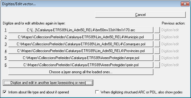 The digitize/edit vector box offers a list from up to 6 layers that had been opened during that session in MiraMon (if there are less, the list is completed with other opened vector layers), favoring those situated in higher positions; this way, with a simple click we can return to digitize/edit over a previously worked layer or an opened layer already. In order to accelerate even further the access to different files during digitalization, each layer of the list is preceded by a numerical value (from 1 to 6) that is allowed to be used as a shortcut on keyboard in order to move not the mouse, in other words, click F2+layer number and continue the task with the new layer whose attributes are being digitized or edited. If the total loaded layer number exceeds 6, the button "Choose a layer among all the loaded ones" allows selection from the total list, as well as alternating between layer names and titles for a possible resolution of doubts. This box also offers another button allowing to explore in order to select other layers, preexisting or not (they must be preexisting ones in case of editing attributes). MiraMon remembers if a layer has been opened previously in digitalize/edit mode or in attributes editing mode, it informs on the list and it applies it conveniently when re-opening it from the box. If a layer has been opened in both modes, the program offers two options. The button In this box, in addition, allows to deactivate the option "Inform about file type and about if opened", an option that reduces the work opportunities via mouse or keyboard, and, in case of structured ARC or POL vectors digitalization, it is allowed to deactivate the option of showing the layer nodes. All the digitization process can be performed without having any background reference map (although it can be unhelpful) or with a background map (loading a raster layer on screen -both IMG, own MiraMon format for raster files as well as any other raster formats opened by MiraMon- and/or other several vector layers -topologically structured or not). In this case, also, during digitalization it is allowed to browse over the map through the scroll bars (or with arrows and "Control+Arrow" combinations) or changing the zoom level through the window zoom, the numerical zoom, the floating bar zoom or the general view in Zoom Menu; the option "Whole view" is useful because it recalculates the total boundary considering everything that has been digitized. This can be done even during the digitalization of a line or polygon, which allows to digitize in a zoom level as detailed as desired. It is also allowed to obtain information of any loaded vector: press F9 to commute the digitalization mode cursor to query mode cursor (or access through the Information Menu) and information about a vectorial object can be requested. During the query, the cursor will take the regular appearance of vector selection and then it will return to the digitalization mode. In contrast, during the digitization obtaining information about rasters is not allowed nor accessing the File Menu. If needed, it is required to finish the digitalization and then reload it over the same file Vector layers digitizationMiraMon allows to digitize non-structured (VEC) and structured (PNT, ARC or POL) vectors with or without verified topology. Reading the document MiraMon vector formats description is recommended in case of not being familiar with MiraMon files. 
Digitization of non-structured vectors When a non-structured vector is digitized the title, the type of attribute and the type of object must be defined in the dialog box "Characteristics of the new vector".  The title of the new vector can contain up to a maximum of 200 characters. However, it is not advisable to use very long names. The title assigned to the vector name is what will appear, for example, in the dialog box "Change order and properties of the layers", which can be different from the name of the file. For example, a vector can be digitized assigning the file name "mcsc.vec" and the title "Map of Land Cover of Catalonia". The attribute or identifier of the objects that are going to be digitized can be text, integer numbers (between -2147483648 and 2147483648) or real numbers. The type of object can be point, line or polygon. When activating Allow dynamic pan during digitization (enabled option by default), the program automatically commutes this option and allows to pan the map by dragging with the mouse as if the hand button or "pan" is already pressed or the dragging has been requested through the Zoom menu when detecting that, after clicking with the digitation button (left button if you are right handed or right if you are left handed and the mouse buttons have been interchanged), an immediate dragging is performed. From this moment, the button can be dropped and work in MiraMon traditional mode, continuing the dragging until a second click is performed. Next, it is possible to access to options of Visualization of POINT, LINE/ARC or POLYGON vectors, according to the type of selected object, where the font type, symbology, border colors, etc, of the objects that will be digitized must selected. In the document MiraMon general visualization characteristics all these options are detailed. Once defined, each time the mouse left button is pressed a new point will be introduced, a new node that will define a fragment of a line/arc or polygon, according to the type of object to digitize. In order to correct any of the digitized elements the button of the digitize/edit toolbar If in digitation non topologically structured vectors have been selected and they must be structured, once they are digitized, the Simplified mode of the Build topology process must be executed, or run the appropriate modules to build points, lines or polygons topology, labelling, etc, in the same Build topology menu (advanced users can also use the corresponding programs from the DOS prompt: VECPNT, LinArc, Ciclar, etc).  In the tutorial Manejo de MiraMon II (up to minute 00:03:20) it is possible to consult an example of digitization of a vectorial layer (original subtitles: in Spanish; authorship: AAECAD). In the tutorial Manejo de MiraMon II (up to minute 00:03:20) it is possible to consult an example of digitization of a vectorial layer (original subtitles: in Spanish; authorship: AAECAD).
Digitization of structured vectors MiraMon allows to digitize structured point, line and polygon type vectors. For all the structured vector families, MiraMon allows to digitize vectors with verified topology or not. For this purpose, the user is consulted, prior to the start of the digitization, what type of structured file of points, lines or polygons is to be digitized (without guaranteed topology or with guaranteed/verified topology): 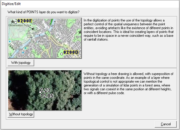  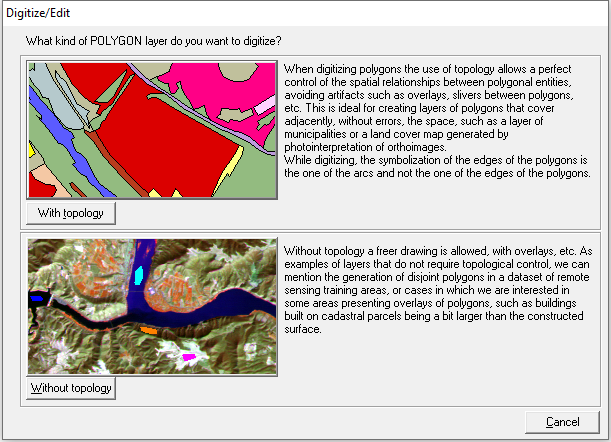 During the digitization process users can convert the option of digitizing with topology to digitizing without topology, either by pressing the button 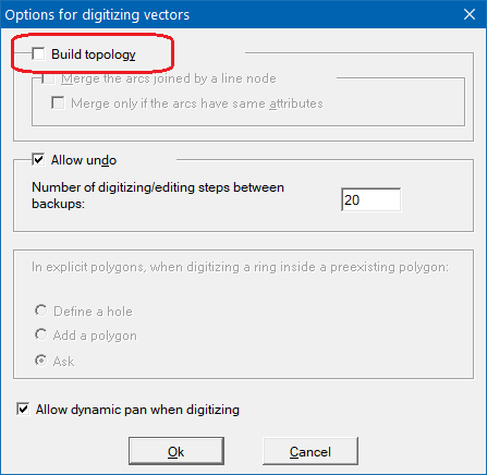 In a polygons layer, to rebuild the polygon topology, it is necessary to chain several applications from the "Edit | Build topology | Polygons" menu: 1. Retrieve the attributes of polygons in the form of labels using the Etiqueta application, available in "Automatic generation of polygon labels". 2. Obtain the edges of the polygons from the arcs of the polygons using the LinArc application, available in "Arcs/Nodes" . 3. Reconstruct the polygons with Ciclar, available in "Polygons". 4. Assign again the attributes of the polygons with the labels obtained in the first step from AtriTop, available in "Graphical objects labelling". This procedure will cut the edges of polygons that intersect and, in the case of coincident edges in space, only one will remain but multiple records will be created to preserve the different attributes on each edge. The polygons will also be reconstructed, already with a verified topology and with the original attributes; in case of coincident zones in space, only one will remain but multiple records will be created to preserve the different attributes in each zone.
In a layer of arcs, to rebuild the topology of arcs/nodes, use the application LinArc, available in "Edition | Build topology | Arcs/Nodes". In the topological structuring process, intersecting lines will be cut and, in case of coincident entities in space, only one will remain but multiple records will be created to preserve different attributes in coincident places.
In a point layer, to rebuild the point topology, use the application VECPNT, available in "Edition | Build topology | Points". In case of coincident entities in the space, only one will remain but multiple records will be created to preserve the different attributes in coincident places.
When a structured vector is digitized, independently from its type, the title of this vector must be defined in the dialog box "Characteristics of the new vector" and, as the case may be, the 3D checkbox must be enabled. Straight away the dialog box "Modify structure of table" appears, to which you can add as many fields as necessary depending on the objects to digitized. MiraMon automatically provides by default different fields according to the type of file to digitize. 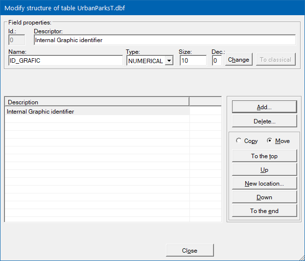 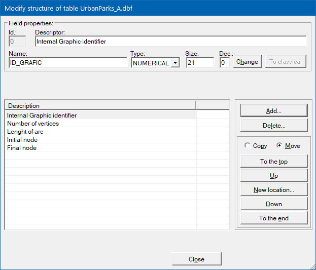 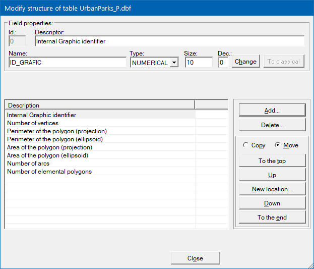 To add a field the button "Add" must be pressed, opening the dialog box "Add field to table". The Descriptor, Name (in capital letters and a maximum extension of 10 characters, without supporting accented letters, etc, due to the limitation of DBF format), type (character, logic, numeric or data) and size (if dealing with the character or numeric type) must be introduced as field properties. When digitizing structured vectors (point, line and polygon type) MiraMon allows multirecord digitization, so more than one record can be introduced for each object. 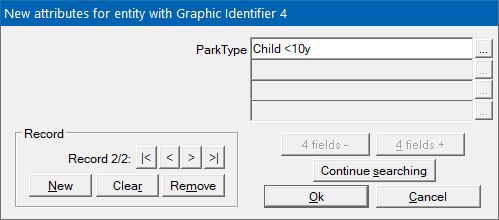 In digitization of point type structured vectors, similarly to the case of non-structured vectors, several visualization options can be selected (show texts, point radius, etc). For further information the document Visualization of point vectors can be consulted; once these options are defined, every time the mouse left button is pushed, a new point is introduced. In case of digitizing arcs or polygons various visualization options (line color, line style and width, etc) can also be chosen. For more information consult "Visualization of line/arc vectors and Visualization of polygon vectors. During the digitizing process, every time the left button of the mouse is pressed a vertex in the line or polygon is introduced. Pressing the right button of the mouse the line or polygon will be finished and the object will be drawn with its definitive color. The last valid vertex is the last one imputed with the left button of the mouse: when the right button is pressed to finish a line or polygon object, the mouse can be at any point of the client area. The same outcome can be obtained through the "Finish object" option from the Edit menu, pressing the F2 key or through the The digitized object suppression is performed similarly to the case of non-structured vectors ( For further information about the actions to perform during digitization, the section Digitize/edit tools can be consulted. IMPORTANT: All digitization and edition processes update (modify) the graphic element files (*.vec, *.pnt, *.arc, *.pol) and the principal associated tables (*.dvc, *T.dbf, *A.dbf., *P.dbf). It is recommended, thus, to make the appropriate backup copies.  In the tutorial Digitizing points in MiraMon it is possible to consult an example of digitization of a topologically point-type structured layer (original subtitles: English; authorship: Abel Pau). In the tutorial Digitizing points in MiraMon it is possible to consult an example of digitization of a topologically point-type structured layer (original subtitles: English; authorship: Abel Pau).
Digitization of structured vectors of polygon type This section has the objective to explain the main differences between digitization of explicit polygons (structured vectors of polygon type without topological structure) and polygons with verified topology. Digitation of structured vectors of polygon type without verified topology (explicit polygons) works similarly to the non-structured files of polygon type but being structured files, each object can be associated with a database and, thus, have as much attributes as needed and of the desired type. By being structured vectors without topology, holes can be added inside the polygons (a feature not admitted in non-structured format) or superimpose polygons if needed, through the digitization of a polygon inside the polygon that encompass it (preexisting "mother" polygon), when MiraMon asks if a new polygon wants to be added or define a hole. 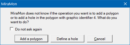 The created explicit polygons can be edited like a non-structured vector: change object attributes, move vertex, insert vertex, delete object, etc. If a hole of one of these polygons has to be deleted, simply one of the erasing options has to be chosen (for example either with key "Del" or through "Edition | Vector edition | Delete object and select it; MiraMon will highlight it with a red colored diagonal pattern and will ask for confirmation or to continue the search. In digitization of structured vectors of the type polygon with verified topology, polygons are obtained from arcs digitization. When users finish digitizing an arc, MiraMon analyze if an enclosed area has been created, i.e., if a polygon (or several ones) has been created and, being so, MiraMon adds it to the corresponding polygon file. In addition, during digitization, arcs which are not linked to any polygon can be accessed directly through the button A feature of digitization of topological polygons is the ability to create an automatic symbolization through the button During digitization of topological polygons, it is also permitted to access to the arcs that have polygons on each side with the same theme attribute through the button It must be taken into account that the digitization of files with more than an arc cycle cannot be updated. For example, if a municipality limit has to be modified and it is cycled over an arc file that has other cycles (regions, provinces...), it must be emancipated, then the limits can be modified and the layer must be cycled again in order to obtain the other cycles. Tools that can be used are Emancipa and Ciclar. In addition, the zero polygon must be defined always. Digitize/edit toolsThe activation of the digitization function can be performed through F2 button or through the menu "Edit | Digitize/Edit vector". Once the digitization is enabled the cursor turns into a special icon  Example of vector digitize/edit toolbar Some icons are not shown active according to the vector typology to digitize/edit Recompilation of digitization options in MiraMon, they are, by order of appearance in the digitize/edit toolbar from left to right and from up to down, the ones which are shown in the following table. By clicking on each link it is possible to access to the explanation of the feature. In the case these options vary according to the vector typology to digitize/edit, the possible options are stated separated by a bar:
End vector digitizing/editingThe completion of the vector digitize/edit process can be made through several options that can be consulted in End digitizing/editing .When reactivating digitization, MiraMon offers to continue with the same file and already existing features. Digitizing scanned mapsScan with an adequate resolution; for on screen digitizing normally it is not needed higher resolution than 120 or 150 dpi, because paper maps usually do not have higher detail. Use B/N mode (1-bit/pixel) or 256 colors, regarding the kind of map; for high quality color ortophotomaps use 24-bit/pixel. Save the file in TIFF, BMP (recommended) formats. Do not use compressed formats because they usually are troublesome and not supported by MiraMon (except for BMP files). In case of compressing the file for exporting or saving, use PKZip or another good compressor: better compressions and less problems will be obtained and less problems. Convert to IMG through proper outer modules (TIFIMG, BNTGA, etc.) or directly read through "File | Open raster" if it is a BMP. In case of digitizing lines with different attributes, such as contour lines, use the MDE256 color palette or, in 256-color systems, the ISO256 palette. Then, the needed control points (3 at least, but 6 or 8 advised) have to be digitized, in a point vector file, to georeference the map. It is recommended to use text attributes and write the map coordinates separated with a comma (ex: 475890,4768920). Then convert this file to a correspondence file (.COR), either manually or through the VECCOR program in the "Tools | Geometry | Convert VEC to PNT" menu. Execute, from the same menu, the program for geometric correction of vectors based on polynomials (CorrGeom).  In the tutorial Georeferenciación de mapas topográficos escaneados (original subtitles: Spanish; authorship: UPC) an example of file georeferencing, both scanned analogical as well as digital without previous georeferencing, can be consulted. In the tutorial Georeferenciación de mapas topográficos escaneados (original subtitles: Spanish; authorship: UPC) an example of file georeferencing, both scanned analogical as well as digital without previous georeferencing, can be consulted.
Digitizing training areas of remote sensing imagesTo digitize the training areas it is necessary to display RGB composite through "File | Open RGB-> 24-bit". Then, open a palette ("Display | New palette") with contrasted colors, like the DIGIT256 or the IBM palette. Digitize the polygons with integer identifiers (values > 0) stating constant color for the boundary and non-constant color inside them. Each group of polygons of the same thematic class will be displayed with the same color, but with different colors than the polygons of other thematic classes. Edit vector attributesMiraMon allows to edit and modify the previously digitized vector attributes (topological structured, non-topological structured and unstructured). This option can also be carried out by pressing Maj+F2. MiraMon remembers if a layer has been previously opened in digitize mode or in attribute edit mode, it informs the layer in the list and it applies the layer conveniently when reopening it from the box. If a layer has been opened in both modes, the program offers both options. The button 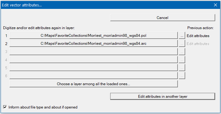 Show the Digitize/Edit toolbarOnce the vector digitize/edit function is enabled, MiraMon allows through Edit | Show the Digitize/Edit toolbar to display in the client area the floating bar with the vector digitize/edit buttons.  Example of vector digitize/edit toolbar Some icons are not shown active according to the vector typology to digitize/edit. It is possible to show, by default, the digitize/edit toolbar when starting a digitize/edit process. It can be configured in the tab "Digitizing" of the box "MiraMon parameters configuration", available through the Help menu; it is also allowed to enable this option through the key "ShowDigitToolBar" of the [MiraMon] section in the MiraMon.par file. 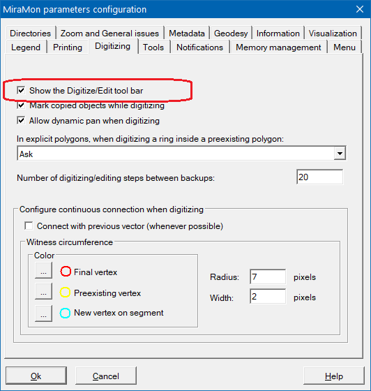 The available options of digitize and edit of vectors are referred in the section Digitize/edit tools. UndoMiraMon allows users to undo the last performed operation. This function can be performed through the button Once the undo option has been selected, the percentage of the evolution of the undo process is reported at the bottom left of the screen.  If during the digitization process an error is produced that does not block the program, MiraMon will try to recover itself and undo the last operation that was being performed. The user will be notified via a message offering the chance of sending an email to get technical support. In the case that MiraMon gets blocked, in the temporary folder the backup copies are stored automatically and the last backup copy can be accessed by the word "giraarc". Unnail last vertex / Cancel commandMiraMon allows users to correct one or more vertexes during the process of introducing line or polygon vertexes through the button Connect upon previous vectorMiraMon allows users to connect vectorial objects with other vectorial objects, both in the file which is currently being digitized as well as any other opened vectorial file, through the buttons of the digitize/edit toolbar 
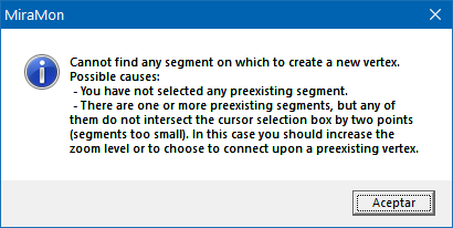 In order to solve this, users must follow the message indications and increase the zoom level and repeat the selection, or either select "Preexisting vertex" if there is no need of such an accurate position. The reference segment does not suffer any change nor an addition of vertex
MiraMon allows users to connect two vertexes automatically via the option named Continuous connection mode or Connect whenever possible. This continuous connection mode allows each click in a digitizing process to establish a geometric connection through the exploration of all the connection possibilities (final vertex, preexisting vertex and new vertex on segment) prior to assume that a new vertex needs to be generated. This mode works with the same tolerance on screen corresponding to the selection cursor window; it is not considered to apply tolerances in map units due to the high risk when working with continuous zoom changes(scale) in order to connect over undesired elements if tolerance is high; or due to being unable to connect over anything if the tolerance is low. 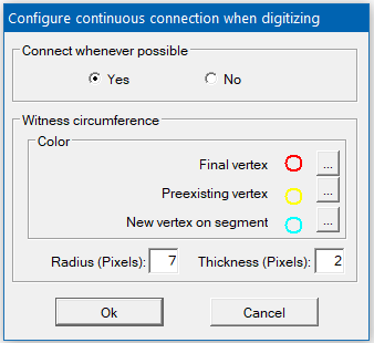 Continuous connection mode is compatible with the punctual requesting of one of the manual connection possibilities. That is to say, if the continuous connection mode is enabled, it can be requested anyways, for example, that a connection over a final vertex want to be performed and with the immediately following click, MiraMon will only explore this connection possibility and, if an entity on which to perform the connection is not found, the program will inform that it is not possible, without generating any vertex. The MiraMon cursor informs at all times if we are in this continuous digitizing mode because it takes in its middle part the appearance of selector (squared) in order to ease the visualization of the elements to which it connects.  Visual information about the result of a connection In classic mode, users are informed about the success of the connection simply because the program does not complain about an unsuccessful connection; in continuous connection mode, users are informed that a connection has been performed and what kind of connection it is, via the design of a small testimonial circumference in the point where the new vertex is generated. The default color of the circumference is:
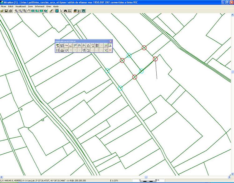 Of course, a click that does not result in any connection does not generate any colored circumference. Testimonial circumferences disappear in the following redraw operation (zoom, F5, etc.). The color, radius and thickness of testimonial circumferences can be configured through the dialog box appearing when clicking on the button Configuration...: 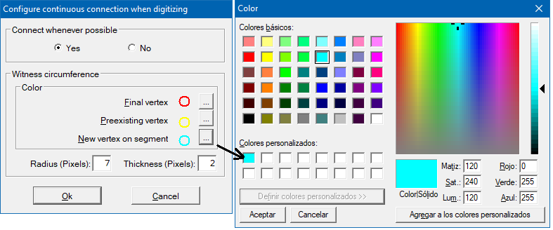 Classic mode keeps being the default mode in MiraMon. In the same session the working mode can be changed through the button "Connect whenever possible". However, if continuous digitizing mode wants to be fixed as the default mode in MiraMon, it can be configured in the tab "Digitizing" in the box "MiraMon configuration parameters" available in the Help menu or either in the key "F3Continuous" of the section [MiraMon] of the MiraMon.par file. Also, colors, radius and thickness of testimonial circumferences can be established via MiraMon configuration parameters or through the keys "ColorVertexFinal_F3Continuous", "ColorVertexIntermediate_F3Continuous", "ColorVertexNew_F3Continuous", "Radius_F3COntinuous" and "Width_F3Continuous" in the section [MiraMon] in the MiraMon.par section. End objectMiraMon finishes digitization of objects and draws the layout of the object of arc/line-type or polygon-type in its definitive color (it is not applied in case of points because the object is ended when digitizing). In the case of non-structured polygons and non-topological structured polygons (explicit polygons), MiraMon closes the polygon when ending the object. In the case of structured polygons with verified topology, this option also ends the object (digitization of the arcs conforming the polygon) though the polygon will only appear in case that the last digitized arc encloses the area. With Activate specific symbolization for polygons digitizing a visualization in the digitization of topological polygons is facilitated. Alternatively, an object also can be ended by clicking the mouse right button. The last valid vertex is the last one entered with the left click: when the right button is clicked in order to finish a line object or polygon, the mouse can be at any place in the client area. In case of points, this option has not any effect because an object of point type is considered ended at the same moment it gets digitized. Change digitizing attributeIn order to change a digitizing attribute, MiraMon offers several options: the button 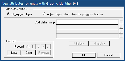 If the attribute belongs to an integer type, MiraMon can increase or decrease automatically its value on each new digitized object. During the digitizing session it is possible to create a file with objects with different attributes or identifiers. If the object type has to be changed it is necessary to close the file (through the button Copy object and attributeMiraMon allows to copy other vector objects from the opened vector files (structured or non-structured) maintaining the original attribute of the copied object, whenever it is possible (it does not admit, for example, texts on a file containing integer attributes) through the button MiraMon avoids copying graphic objects that are inconsistent with the file it is being digitized, or it adapts them as necessary (for example, if digitizing points, MiraMon will only copy a single vertex). When copying from a structured vector containing polygons (.pol), it will only copy the selected ring, without considering other rings the polygon can contain. In the case of copying objects of line or arc type, if there is a part of the copied line or arc from that is not interesting, the object can be cut with the function "Break line" and delete the undesired part through "Delete object". If more than one object is needed to be copied, select the first one with the right button; this allows you to obtain the copy and continue copying more objects. In case the "Highlight copied objects" option is activated, the objects that are copied are assigned a different color, which MiraMon determines in order to obtain the best visualization. The default value used to highlight copied objects can be modified via MiraMon parameters configuration available in the Help menu, in the Visualization tab, in the section "Selection color", or either with the key "MarcaObjecteCopiat" in the section [MiraMon] of the MiraMon.par file. For further information "Visualization | Selection color" can be consulted. In case of not having the option "Highlight copied objects" enabled, the assigned color will be the final corresponding color by the defined attribute. To finish the copy of the object and attribute, the last object to copy must be selected using the left button, or pressing the backspace button or simply clicking with the left button on an area where no objects to copy exist. In order to copy an object (and keep the current attribute) Copy object (current attribute) can be consulted. Copy object (current attribute)This option is similar to the previous one. It is different in the fact that it allows you to copy other vectorial objects based on other vectors currently open (structured or non-structured), assigning the current active attribute. To copy the object and continue with the active attribute, the button Close polygonMiraMon allows users, in the case of polygon type files (structured or non-structured), to close the polygon being digitized via the button Highlight copied objectsMiraMon allows to display the object being copied, using the appropriate selection color. This is useful to see the scope of the copied objects when the same color or palette is used for the digitizing file and for the file providing the objects to copy, and to know whether it is necessary to cut them and where. The menu "View | Selection color" allow to control the color with which selected objects are shown. The default value used to highlight copied objects when the program starts can be established through MiraMon parameters configuration available via the Help menu, in the Visualization tab, in the section "Selection color", or either through the key "MarcaObjecteCopiat" in the section [MiraMon] of the MiraMon.par file. Coordinate entry via keyboardMiraMon allows to digitize the vectors by typing in their coordinates through the keyboard, via the button Users can choose between digitizing by introducing the coordinates of all the objects via keyboard (button "Enter coordinate and continue via keyboard") or either enter a coordinate via keyboard and continue with the mouse ("Enter coordinate and continue via mouse"). If data is copied from the clipboard, X, Y and eventually Z, or of angle and distance and eventually Z, separated by colons, spaces or tabs, data is distributed automatically in the 2 or 3 corresponding boxes. In order to eliminate the last coordinate entered, simply press the corresponding button of this box. To finish the digitization, press "End object". The button "Close" allows to return to the client area without closing the digitization.  Options for digitizing vectorsMiraMon allows users to select several options in vector digitization. Options on vector topological structuration MiraMon allows users to choose, in the digitization of structured vectors, if the objects to digitize must have verified topology or not. For all of the structured vectors type, during the digitization process, users can change to digitization without granted topology (through the Options box in the vector digitizing), simply by disabling the corresponding box. When disabling topological structuring, any of the options explained down below is also disabled. Reading the document MiraMon vector formats description is highly recommended in case of not being familiar with MiraMon files.
In the case of topologically structured vectors of arc type and polygon type, vector digitizing options allow to enable the possibility to merge the arcs joined by a line node (in case that the two arcs that were separated by a node have different attribute, a multirecord attribute is created in the resulting arc from the merging of the two previous arcs) or, just merge when the arcs to join have the same attribute. It is also allowed to choose the option of asking what management to perform in case of joining two objects, whether polygons or arcs, with different attributes for each element. For more information, the Join consecutive arcs/lines and Join adjacent polygons or consecutive arcs/lines section can be consulted.
In the case of structured vectors of polygon type without verified topology (explicit polygons), any option of topological structure is not permitted because prior to the beginning of digitization users have been consulted about the type of polygon to digitize and the option "without topological structure" has been selected. So, it does not apply the topological structure options and only it is allowed to select in the section of explicit polygon (without verified topology) digitization if during a ring digitization it must be interpreted that the ring: This choice can be made permanently from the current MiraMon session through Edition | Options for digitizing vectors or either by clicking the button
Options of undo This menu also allows to determine the number of digitizing/edition steps that are allowed to be done between backups. The default value is 20. Options of dynamic pan Through this menu it is allowed to enable dynamic pan when digitizing and select the number of steps that can be undone of the digitize/edit. End digitizing/editingMiraMon allows user to end the current digitizing or editing process by pressing the button 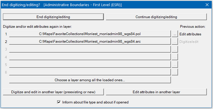 Once digitization has ended, it is permitted to access to File menu as well as starting a new digitizing process on another file. Edit vectorThis menu allows you to perform changes on an opened vector file with "Digitize | Edit vector". Before erasing or changing an attribute, the object is highlighted with another color and confirmation is requested; in case of accepting, the change is updated in the original file. It is recommended, in case of not being sure about the changes to do, to make a backup. Point objects can be selected by clicking at their insertion point. Line or polygon objects (non structured) can be selected by clicking on any of their segments, although the process of locating the object is faster if you select a vertex. In structured polygon files, objects can be selected by clicking inside the polygon as well as selecting a segment or a vertex. The different vector editing options depend on the vector typology, thus, only those options corresponding to the typology of the vector which is being edited will be selectable. Down below, all those options are stated, which are also available through the digitize/edit toolbar: Show vertices: It shows, with little white circles, the position of the vertices of the lines and polygons. These marks will disappear in the next redrawing. Pressing Ctrl+F2 or the If more than one object has to be shown, the option to show vertices has to be abled and select the first one with the right button; this allows to obtain the desired effect and at the same time, leaving the cursor in the consulting mode Break arc/line in vertex: Splits a preexisting line/arc object in two at one of its vertices. A black circle indicates the point where the line has been broken. This mark will disappear in the next redrawing. In case of not being sure about the location of the vertices, execute "Show vertices". Pressing Ctrl+F3 or the In order to break a line in more than one object, the option to break arc/line in vertex has to be abled and select the first one with the right button; this allows to obtain the desired effect and to continue with more objects. To stop breaking arc/line in vertex and return to the digitizing option, select the last object using the left button, press the backspace key or simply click with the left button on an area where no objects exist. Break arc/line: Splits a preexisting line/arc object in two, creating a new vertex (intermediate) at the selected point if it is in a segment. Pressing Ctrl+Maj+F2 or the button Join consecutive arcs/lines: Allows to join two previously digitized arcs or lines. To join the arcs/lines the two vertices to join have to be selected. Pressing Ctrl+U or the button 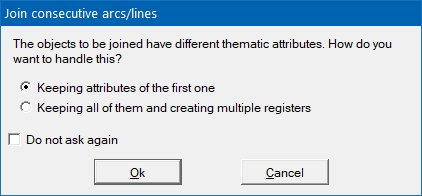 In case of enabling the option of Do not ask again, the program will apply the same solution previously chosen. If the user later wants to be asked again, access to the Options on vector topological structuration and re-enable the options of "Ask when joining polygons when attributes are different" or "Ask when joining arcs when attributes are different", as appropriate. Join adjacent polygons or consecutive arcs/lines: It allows to join two adjacent polygons previously digitized, as well as it allows, in the digitization of the layer of arcs that form the edges of the polygons, the union of consecutive arcs digitized previously. In order to join the polygons or the arcs, it is required to select both elements to be joined. Pressing Ctrl+U or the button 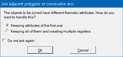 In order to join two objects of which at least one has a blank record, the following attribute assignment criteria will be applied to the object resulting from the join:
Blank vs A = A Where "Blank" is the blank record of one of the objects and "A" is any attribute (that is, it is not a blank record). When one of the two objects to be joined has a blank record and the other object has a multiple record (two different attributes, indicated by a slash "/" in the example below), the following criterion of attribute assignment will be applied to the object resulting from the join:
Blank vs B/A = B/A Blank vs Blank/Blank = Blank Split polygons (structured polygons with verified topology): It allows to break a polygon by tracing the splitting line that will generate two polygons assigning the current attribute (in memory) to the resulting smaller polygon (it is possible to consult the current attribute and change it if necessary by pressing F4). Polygons without verified topology cannot be splitted. Eliminate vertex: It allows to erase a vertex in a line, arc or polygon file by joining the preceding vertex and the following one to the one which is eliminated. By pressing Ctrl+E or the button Insert vertex: Allows to insert a vertex in a line, arc or polygon file, without splitting the line at the point where the vertex has been inserted. Pressing Ctrl+I or the button Move vertex: Allows to move vertices in point, line/arc and polygons files (either structured and non-structured). Pressing Ctrl+M or the button If the file is a 3D file, the movement is in 3D, being able to add, for example, multizets or simply change the Z position of a vertex. When moving a vertex, the function to connect on a previous vertex (F3) is still enabled; if the vertex to move is a 3D vertex, it will inherit the position X, Y, Z of the point where it has been connected from, unless there is not an existing Z value for that point, a case where the Z it had before being moved will be kept (if then the Z wants to be turned into NoData, it can be moved via keyboard and simply erase it). In case of structured files with verified arc topology, if the movement of the vertex implies the creation of new nodes, they will be calculated automatically. In the case of structured polygons, the vertex movement will only take place if the result does not imply changes on topology or new cuts with other arcs assigned to polygons with only one single exception, when the movement implies A SINGLE cut: in this case, determinations about the file topology are taken automatically. Tools for creating, joining, and/or eliminating polygons, among others, can be used to make changes that involve changes in the topology of the layer. If there is no vertex in the selection square of the cursor, but there is a segment, the vertex moved will be the closest one to the segment. This is useful for finding which line the vertex to be moved corresponds to in situations with two or more lines that converge on the same vertex; in this situation, instead of choosing the vertex directly (which is conflictive because there is more than one vertex belonging to different lines in the same position), select the arc that contains the vertex to be moved (if it is appropriate, use zoom) in a position near the vertex to be moved (closer than the previous vertex of the same arc). In case of structured polygons with verified topology, the movement is always from an intermediate vertex or, if several arcs come together in a node, the movement will be from the whole node as a unit, also updating all the parameters of the new topological configuration (recalculation of areas, etc). Move/edit vertex by coordinate: This function is similar to the previous case, but using the keyboard. Pressing Ctrl+W or the button 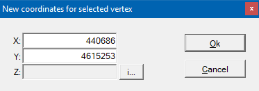 Change arc/line direction: Allows to change the direction of a line file with respect to the direction in which it was digitized. Pressing Ctrl+S or the button  Change object attribute: Allows to change the attribute or the identifier of the object (text, integer or real). In the case of identifiers (index in a data base file) this operation must be done very carefully. If a change is done, the color of the object immediately changes on the screen. Pressing Ctrl+F4 or the button In order to change the attribute of more than one object, the option of changing the attribute of an object needs to be enabled and select the first one with the right button; this allows to obtain the desired effect and leaves the cursor in consulting mode Delete object: Allows to erase objects of the file (points, lines, arcs or polygons), with previous confirmation of the action. Pressing the key "Del" or the buttons In the case of structured polygons (with verified topology or without it -explicit polygons-) it is allowed to delete the areas which are not assigned to any polygon (inside polygons or spaces between polygons). When some of these spaces wants to be deleted, the option delete object needs to be chosen and select the space in the same way a polygon is selected (a red layout appears to state the area that wants to be treated):
 If you need to delete more than one object, select the first one with the right button; this allows to obtain the desired effect and to leave the cursor in consulting mode Delete objects: It allows to delete several objects at once through the combination of the keys "Ctrl+Del" or the buttons Group polygons: It allows to group polygons during their digitization so that they conform the same set of polygons as long as they are discontinuous polygons (such as enclaves) or that they share a node. Currently it is not allowed to group polygons that share one or more arcs; in these cases the join adjacent polygons function is recommended. Once the object selecting tool appears, the polygons to be grouped need to be chosen. Pressing Ctrl+G or the button Ungroup polygons: It allows to ungroup polipolygons (a polygon conformed by a set of polygons) during their digitization. Once the object selecting tool appears, the polipolygon to be ungrouped needs to be chosen. Pressing Ctrl+D or the button Reorder polygons: It allows to change the "vertical" order of explicit polygons (it does not make sense in polygons with verified topology because there is no polygon overlapping). Once the object selecting tool appears, the polygon to be rearranged needs to be chosen and, consecutively, the new position between the ones shown as available need to be chosen. Pressing Ctrl+R or the button Navigation by arcs not related to any polygon: In the case of structured polygons with verified topology this window shows the list of arcs that does not enclose any polygon, that is to say, that are not linked to a polygon. It is a very useful tool when finishing a digitization, as it allows to verify the resulting topology. This could be because several reasons: a line that sets the separation between two areas has been traced but it has not been sent to any other arc in order to create a complete area; an arc crossing with another arc but it has not been set out enough and it fell short or exceeded. Pressing Ctrl+N or the button  When an arc is selected via browsing through the table lines or through the buttons at the bottom part of the window, MiraMon zooms the area where there is an arc in order that users can decide what to do with the selected arc: remove it (through the selection of the "Delete" button) or modify its layout via any of the described vector editing tools. MiraMon also allows users to erase all the arcs not enclosing polygons in a single action via the button "Delete all". The button "Zoom to all" moves the screen-view to the area containing all the arcs without an assigned polygon (useful when they are located in a concrete area in the map). Activate specific symbolization for polygon digitizing: In the case of polygons with verified topology, symbolization of the edges of the polygons is the one of the arcs and not the one of the polygon edges. This option allows users that have not thought on any symbolization to enable a symbolization that lets them distinguish the polygons by attributes (the interior of polygons with the first thematic attribute that users had created is symbolized) as well as the arcs that are not assigned to any polygon (colored in orange and with dashed lines) and lets them visualize what is below the polygons (a transparency of 70% is applied to polygons). Pressing Ctrl+A or the button  Navigation by adjacent polygons with the same thematic attributes and other possible topological problems: In the case of structured polygons with verified topology, this window shows the list of arcs that have polygons sideways with the same thematic attributes or wither with one from the two attributes is empty (or both). In addition, the arcs of polygons that have blank attribute and are neighbors of the zero polygon, and those that delimit empty polygons are shown. This could happen due to several reasons: a polygon has been splitted and one of the attributes has not been changed or either an arc creating a polygon without attribute or a wrong attribute has been traced. It is a very useful tool when finishing a digitization, as it allows to verify the resulting topology. Pressing Ctrl+V or the button  When an arc is selected via browsing around the table lines or through the buttons at the bottom part of the window, the program zooms the area where there is the arc that separates both polygons with the same thematic attributes or with empty attributes in order that users can choose what to do with those polygons: joining them (which can be performed with the button "Join polygons" if enabled) or modify the attributes of one or both polygons. If the "Join Polygons" button is not enabled, the user can fill the empty space with another polygon (by deleting the blank space, for example). The button "Zoom to all" takes the screen-view to the area where all the polygons showing this feature are (useful when they are located in a concrete area in the map). The "Join all" button allows the user join all adjacent objects that have a chance to be joined according to the following criteria:
Build topologyThis menu provides access to several functions needed to build topology. These processes convert non-structured vector files -VEC- or structured vector files (PNT, ARC/NOD, POL) without topology, obtained by digitizing, by automatic raster->vector conversion through MiraMon or by importing from other formats such as DXF, SHP, etc, to structured files with verified topology (PNT, ARC/NOD, POL). These functions are implemented in external modules (note that in the menu they are preceded by an asterisk '*'). This implies: * The files involved do not need to be opened from MiraMon. * It is possible to launch a process and to leave it running in the background while working with MiraMon or another application, because MiraMon automatically launches these processes in multitasking. * The running parameters can be introduced from the command line. So a BAT files can be written to do repetitive tasks. * The running parameters can be introduced in Windows dialog boxes even when running in DOS boxes. Simply execute the program name preceded by the letter "W". For example, to execute CreaTop, type wCreaTop and the CreaTop's Windows interface will appear. If working under Windows 9x or NT, start '"W" programs directly from the command line. * To obtain more complete help for any of these modules, click on the MiraMon menu and press the "Help" button on the parameters dialog box. To get help from the command line type the program name followed by a question mark (CreaTop ?); if no question mark is given, the syntax without help will appear. Following is a brief description of the existing modules related to building topology. Simplified mode (CreaTop): This module allows to build topology of points, lines or polygons with minimum user interaction; only a few parameters are required: the input file name (which will automatically be the output file name), which type of entities have to be obtained (points, arcs/nodes or polygons) and a generic tolerance. In the case of polygons, in addition, the file containing the labels needs to be established. 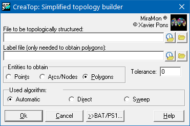 The philosophy of this module is to be useful when no sophisticated characteristics are needed and the digitizing process has been done following the right connectivity rules. Also, non-expert users will find in this module a simple way to obtain the topologically structured vector layers they wish. More information can be obtained at CreaTop. Nevertheless, in order to obtain full control of the process of polygon labelling (which label has priority, etc), to control what to do when more than one database record exists for each graphic entity, to introduce specific tolerances for nodes and arcs, etc, the advanced modules described below will be needed. Points (VECPNT): This module allows transforming non-structured point files (VEC) into structured point files (PNT) with or without topological structure and vice-versa, it also allows to structure topologically a structured point file (PNT) by joining the points that stay inside a certain distance. In order to proceed to the topological structuration of points, the type of desired transformation needs to be determined (VEC->PNT or vice-versa, PNT->PNT), establish the input folder, the output folder, the field descriptor that determines the attribute (in case of existence), the name of the field in the database to create and a generic tolerance. Via the button "Advanced" users can access to determine which option is desired in order to find empty records, options in case to add altitude, etc. For further information the module VECPNT can be consulted. 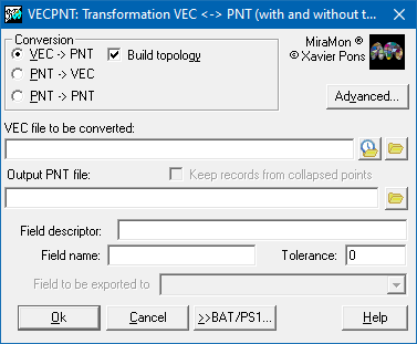 Arcs/Nodes (LinArc): This module allows the transformation between line vectorial files (VEC) and line structured files (ARC) with or without topological structure and vice-versa, as well as structure topologically a line structured file (without verified topology) and simplify an ARC file by joining the arcs that fulfill certain conditions. For further information the module LinArc can be consulted.  Polygons (Ciclar): This module allows to create polygons with topological structure (POL) from an arc file (VEC, ARC), convert polygons from a POL file to a VEC file through ungrouping each polygon group in their elemental polygon as well as simplifying (recycling) a polygon file joining or merging the polygons that fulfill certain conditions, for example, those who are touched by a node and share the same theme attributes, etc. For further information the module Ciclar can be consulted. 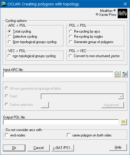 Polygon labelling (AtriPol): This module allows to label structured polygons. The attributes to transfer (labelling file) can be contained on a graphic file of points (PNT or VEC of points) or in a DBF table containing fields MAPX and MAPY. Labelling in multiple registers is permitted. For further information the module AtriPol can be consulted.  Labelling graphic objects (AtriTop): This module allows to label structured polygons. The attributes to transfer (labelling file) can be contained on a graphic file of points (PNT or VEC of points) or in a DBF table containing fields MAPX and MAPY. Labelling in multiple registers is permitted. For further information the module AtriTop can be consulted. 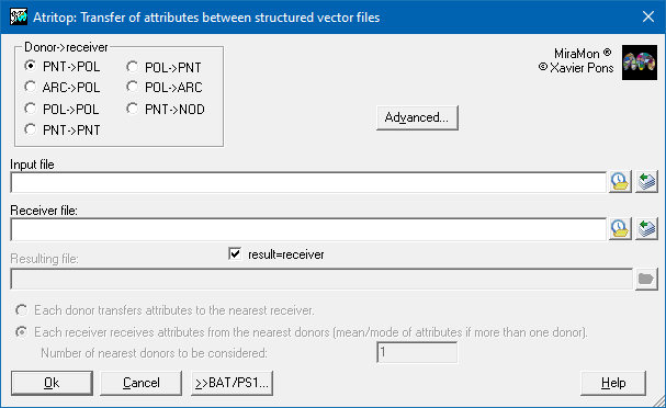 Test topology (TestTop): This module allows to perform consistency tests over structured files (particularly under a thematic point of view) that structuration programs does not perform. For further information the module TestTop can be consulted. 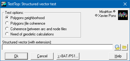 Erasing micropolygons (MicroPol): This module allows to delete micropolygons from a polygon file or a categorical raster according to one or more features (very small area, very small area/perimeter relationship, etc). For further information the module MicroPol can be consulted. 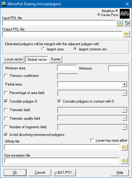 Automatic generation of polygon labels (Etiqueta): This module allows to generate points that are polygon labels as of a POL file or a VEC file of explicit polygons, etc. For further information the module Etiqueta can be consulted. 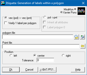 |